CNC Turning Tolerances and Fits: A Practical Guide for Shafts and Bushings
A practical guide to shaft and bushing tolerances, fits, runout, surface finish, inspection methods, cost drivers, and RFQ requirements for CNC turned parts.
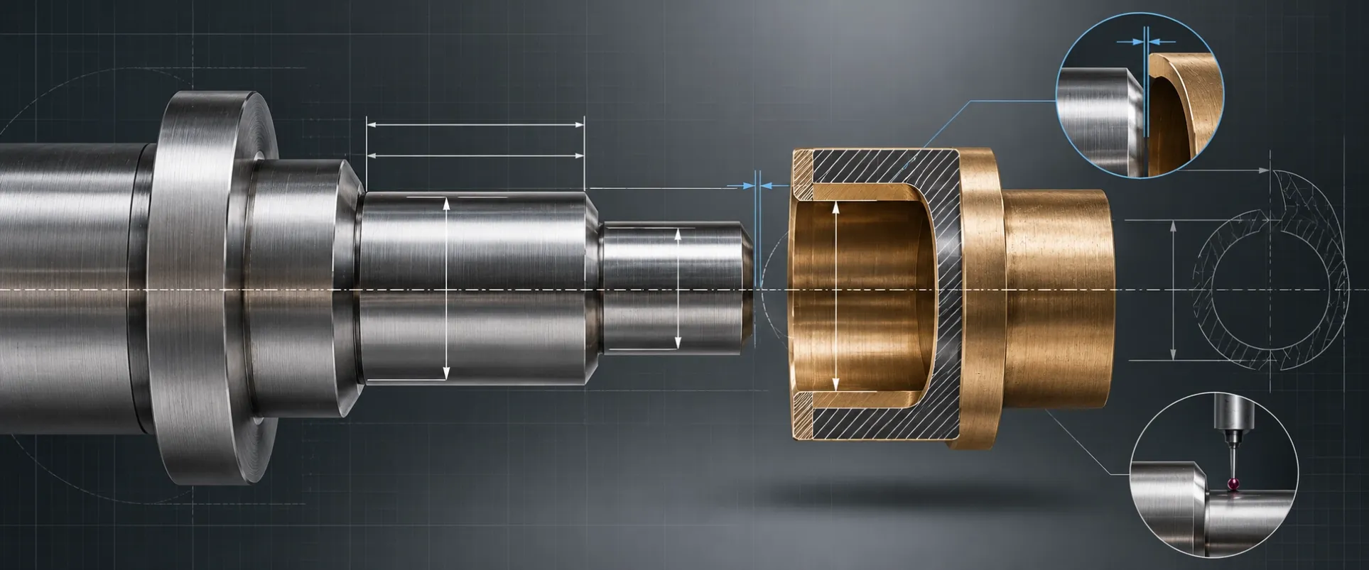
CNC-turned shafts, bushings and mating components often fail for a simple reason: the drawing specifies a tight size but does not fully define how the parts must fit, rotate, seal or be inspected. A useful tolerance plan starts with function, not the smallest number a machine can hold.
This guide explains how to define dimensional tolerances, fits, runout, surface finish and inspection requirements so suppliers can quote accurately and manufacture parts that assemble reliably.
Quick answer: what tolerance should you specify?
Use the loosest tolerance that still protects function. General turned dimensions may often use a wider tolerance, while bearing seats, sealing diameters, press-fit features and datum-related surfaces receive tighter controls. Do not apply one tight tolerance to every dimension.
| Feature | Typical design priority | What to define |
|---|---|---|
| Free outside diameter | Cost and manufacturability | General size tolerance |
| Bearing or seal journal | Fit, wear and leakage | Size, finish, roundness and runout |
| Bushing bore | Clearance and alignment | Bore size, cylindricity and finish |
| Shoulder face | Axial location | Length, perpendicularity and face runout |
| Thread | Assembly and load | Thread standard, class, depth and gauge method |
Important: values on a drawing must be reviewed against material, diameter-to-length ratio, wall thickness, heat treatment, surface finishing, quantity and inspection method. Capability on one feature does not imply the same tolerance is economical on the whole part.
1. Start with the functional relationship
Before selecting a tolerance, describe what the feature does. Does a shaft rotate in a bushing? Does a bearing need a locating fit? Must a piston slide without sticking? Does a seal run on the diameter? Is the part assembled at room temperature but operated hot?
The answers determine whether the critical requirement is clearance, interference, position, runout, surface roughness or a combination of these. A diameter can be within size tolerance and still fail if it is tapered, lobed or eccentric to the datum axis.
2. Calculate clearance or interference
For a shaft and bore, the basic relationship is:
Clearance = bore diameter − shaft diameter
Example: a bore specified as 20.020–20.040 mm and a shaft specified as 19.980–20.000 mm produces:
- Minimum clearance: 20.020 − 20.000 = 0.020 mm
- Maximum clearance: 20.040 − 19.980 = 0.060 mm
This 0.020–0.060 mm range is more useful than discussing either part alone. If both mating parts are supplied by different vendors, include the limits and the intended functional clearance on the assembly drawing.
For an interference fit, the same calculation produces a negative clearance. Confirm assembly method, material strength, wall thickness, temperature and whether parts will be pressed, heated or cooled during installation.
3. Size tolerance is not form control
A size tolerance controls measured diameter limits, but it may not adequately control roundness, cylindricity, straightness or taper. For precision journals and long bores, consider whether separate geometric controls are necessary.
- Roundness limits variation of each circular cross-section.
- Cylindricity controls the entire cylindrical surface.
- Straightness can control an axis or surface element.
- Total runout controls cumulative variation while the part rotates about a datum axis.
- Perpendicularity helps control shoulders that locate bearings or spacers.
Avoid stacking redundant controls. If the function is rotation relative to a datum axis, runout may communicate the requirement more directly than several unrelated coordinate dimensions.
4. Runout and datum selection
Runout requirements are only meaningful when the datum reflects how the part functions or will be inspected. A common shaft strategy is to establish the primary datum from the functional bearing journals, then control other rotating diameters and faces relative to that axis.
Questions to answer on the drawing:
- Which surface establishes the rotation axis?
- Should the part be inspected between centers, in a chuck, on V-blocks or in a fixture?
- Is circular runout sufficient, or is total runout required over the full surface?
- Does heat treatment occur before or after final machining?
Long, slender parts can bend under clamping or measurement force. State any free-state requirement and discuss straightening or support strategy before production.
5. Surface finish must match the function
Surface roughness and size tolerance solve different problems. A polished-looking surface is not automatically dimensionally accurate, and a diameter within tolerance may still be unsuitable for a dynamic seal.
| Application | Finish concern | Additional review |
|---|---|---|
| Bearing journal | Wear and seating | Roundness, runout and grinding need |
| Dynamic seal surface | Leakage and seal life | Lead pattern, scratches and coating |
| Sliding bushing | Friction and oil retention | Clearance, lubrication and material pair |
| Press fit | Assembly force | Surface damage and edge condition |
| Cosmetic diameter | Appearance consistency | Tool marks and finishing process |
Specify Ra only where it serves a function. If waviness, lay direction or sealing performance matters, add the appropriate requirement rather than relying on one roughness value.
6. Material and process effects
Tolerance cost changes with material and process sequence. Aluminum is easy to cut but thin sections may distort. Stainless steels may work-harden and generate heat. Hardened steel may require grinding after heat treatment. Engineering plastics can move with temperature, moisture and measurement force.
Also consider plating, anodizing, passivation, nitriding or PVD coating. A coating changes dimensions, and the drawing should state whether limits apply before or after finishing. For mating diameters, identify masking requirements and the expected coating build-up.
7. Practical tolerance allocation
A cost-effective drawing separates features into three levels:
- Functional critical features: directly affect fit, sealing, rotation, safety or assembly.
- Interface features: locate the part relative to other components but allow moderate variation.
- Non-critical features: can follow a general tolerance block.
This prevents unnecessary inspection and reduces scrap risk. Tight tolerances increase the need for controlled temperature, stable workholding, tool compensation, additional process steps and more capable measurement equipment.
8. Inspection plan for shafts and bushings
Agree on the inspection method before production. A micrometer may be appropriate for an accessible outside diameter; bores may require bore gauges, air gauges or a coordinate measuring machine depending on size and tolerance. Runout typically requires a defined setup and indicator location.
An effective inspection plan records:
- Drawing revision and part number
- Feature identification and nominal value
- Upper and lower limits
- Measured result and instrument
- Sampling level or 100% inspection requirement
- Material and finish certification when required
- Measurement temperature for temperature-sensitive work
Ask for a sample inspection report before the production order if documentation format matters to your quality system.
9. Common drawing mistakes
- Applying ±0.01 mm to every dimension without functional justification
- Specifying a shaft diameter without the mating bore limits
- Using size tolerance to imply concentricity or runout
- Omitting the datum axis for rotating features
- Ignoring coating thickness on fitted diameters
- Leaving sharp edges undefined near seals or assembly interfaces
- Not stating whether dimensions apply before or after heat treatment
- Requiring a surface finish that cannot be verified with the planned method
10. RFQ checklist
For a faster and more accurate CNC turning quotation, provide:
- 2D drawing with datums, tolerances and revision level
- STEP or other 3D model for geometry review
- Material grade and condition
- Prototype and annual production quantities
- Heat treatment and surface finish requirements
- Mating-part limits or required clearance/interference
- Critical-to-quality feature list
- Inspection report, material certificate or traceability requirements
- Packaging and delivery requirements
Frequently asked questions
Can every diameter be held to ±0.002 mm?
No. Such a tolerance may be achievable on suitable features, but it depends on geometry, material, process route, thermal control and inspection capability. It should be applied only where function justifies it and after engineering review.
Should I specify a tolerance or an ISO fit?
Use the system your engineering team and supplier can interpret consistently. An ISO fit designation is useful for standardized mating relationships, while explicit upper and lower limits make the acceptance range immediately visible. For global sourcing, many buyers include both where appropriate.
When is grinding needed after turning?
Grinding may be considered for hardened materials, very tight size or form control, fine finishes, or critical bearing and seal surfaces. The decision depends on the complete feature requirement, not diameter tolerance alone.
How can I reduce the cost of tight-tolerance turned parts?
Limit tight controls to functional features, avoid unnecessary tolerance stacking, define realistic inspection methods, allow stable fixturing surfaces, confirm finish build-up and separate prototype requirements from production controls.
Send a drawing for engineering review
If you are sourcing custom shafts, bushings, sleeves, pins or other turned components, send the 2D drawing, 3D model, material, quantity and inspection requirements. Zync Precision can review manufacturability, identify missing fit information and prepare a clear quotation for prototype or production quantities.
Advanced ISO 286 calculation: 20 mm shaft and bore
ISO 286 separates two ideas: the IT grade controls tolerance width, while the letter controls the location of the tolerance zone relative to the zero line. Uppercase letters describe holes and lowercase letters describe shafts. In the hole-basis system, an H hole has a lower deviation of zero.
The following worked example uses a nominal diameter of 20 mm, which falls in the over-18-to-30 mm diameter step. ISO calculations use the geometric mean of the step:
D = √(18 × 30) = 23.24 mm
For this size range, the standard tolerance unit is calculated in micrometres:
i = 0.45 × ∛D + 0.001D = 1.31 µm
- IT6 = 10i ≈ 13 µm
- IT7 = 16i ≈ 21 µm
Published limit deviations should always be checked against the applicable edition of ISO 286-2. The calculations below show how the limits and resulting clearance are interpreted.
Worked example A: 20 H7/g6 running clearance fit
| Feature | Lower deviation | Upper deviation | Permitted size |
|---|---|---|---|
| 20 H7 bore | 0 µm | +21 µm | 20.000–20.021 mm |
| 20 g6 shaft | −20 µm | −7 µm | 19.980–19.993 mm |
Minimum clearance occurs with the smallest bore and largest shaft:
20.000 − 19.993 = 0.007 mm
Maximum clearance occurs with the largest bore and smallest shaft:
20.021 − 19.980 = 0.041 mm
Therefore, the theoretical clearance range is 7–41 µm. This may suit free-running or accurately guided motion, but suitability still depends on load, speed, lubrication, temperature, surface finish, alignment and the length of engagement.
Worked example B: 20 H7/h6 close clearance fit
| Feature | Lower deviation | Upper deviation | Permitted size |
|---|---|---|---|
| 20 H7 bore | 0 µm | +21 µm | 20.000–20.021 mm |
| 20 h6 shaft | −13 µm | 0 µm | 19.987–20.000 mm |
- Minimum clearance: 20.000 − 20.000 = 0.000 mm
- Maximum clearance: 20.021 − 19.987 = 0.034 mm
This fit can approach line-to-line contact at maximum material condition. It should not be described as guaranteed free running without considering form error, finish, temperature and assembly conditions.
How to compare clearance, transition and interference fits
| Fit behavior | Limit calculation | Typical design questions |
|---|---|---|
| Clearance fit | Smallest bore is larger than largest shaft | Required oil film, speed, alignment and backlash |
| Transition fit | Limits can produce either small clearance or small interference | Assembly repeatability, location accuracy and removal |
| Interference fit | Largest bore is smaller than smallest shaft | Contact pressure, hub stress, torque transfer and assembly force |
For a press fit, diameter limits alone are insufficient. Engineering review should consider hub outside diameter, engagement length, elastic modulus, yield strength, edge chamfers, surface finish, lubrication, assembly speed and operating temperature. Thin hubs can expand or crack even when the nominal interference appears reasonable.
Thermal expansion can consume the clearance
Dimensional limits normally apply at the specified reference condition, but parts may operate at a different temperature. A first-order diameter change can be estimated with:
Δd = α × d × ΔT
For a 20 mm steel shaft with α = 11.5 × 10⁻⁶/°C and a 40°C temperature rise:
Δd = 11.5 × 10−6 × 20 × 40 = 0.0092 mm
For a bronze bushing using α = 18 × 10−6/°C at the same temperature rise:
Δd = 18 × 10−6 × 20 × 40 = 0.0144 mm
If both parts experience the same uniform temperature change, this simplified example increases diametral clearance by approximately 0.0052 mm. Real assemblies may behave differently because the shaft and housing can run at different temperatures and the bushing is constrained by its housing. Use actual material data and operating temperatures for design verification.
Tolerance stack example for axial location
Suppose a shaft assembly has three serial dimensions controlling an end position:
- Shoulder A: 12.00 ±0.03 mm
- Spacer: 8.00 ±0.02 mm
- Bearing width: 10.00 ±0.01 mm
The nominal stack is 30.00 mm. Worst-case tolerance is the arithmetic sum:
Worst-case variation = ±(0.03 + 0.02 + 0.01) = ±0.06 mm
If the assembly requires ±0.04 mm, tightening only the final shaft length may not solve the problem. The datum scheme and each contributor must be reviewed. Statistical stacking can be appropriate for stable high-volume processes, but its assumptions and acceptance criteria should be agreed before use.
Measurement capability and decision rules
A 13 µm shaft tolerance cannot be protected reliably by a measurement process with similar uncertainty. As a practical example, an expanded measurement uncertainty of 3 µm consumes about 23% of a 13 µm tolerance width:
3 ÷ 13 × 100% = 23%
This does not automatically make the measurement unacceptable, but it increases decision risk near the limits. The inspection plan should identify the instrument, calibration status, resolution, measurement force, temperature control, sampling plan and agreed decision rule. ISO 14253-1 addresses decision rules for proving conformity or nonconformity; ISO 14253-2 provides guidance for estimating measurement uncertainty.
| Feature | Common inspection method | Risk to control |
|---|---|---|
| External journal diameter | Outside micrometer or comparative gauge | Temperature, operator force and lobing |
| Precision bore | Bore gauge, air gauge or CMM | Taper, alignment and master setting |
| Circular runout | Indicator with defined datum setup | Fixture error and datum simulation |
| Roundness | Roundness instrument | Filtering and number of measured sections |
| Surface roughness | Profilometer | Cut-off, evaluation length and lay direction |
Engineering release checklist for a fitted diameter
- State nominal size and ISO fit or explicit upper and lower limits.
- Identify whether limits apply before or after coating and heat treatment.
- Define the functional datum axis and required runout or form control.
- Specify surface texture only where it supports bearing, sealing or sliding function.
- Calculate minimum and maximum clearance or interference.
- Check operating temperature, lubrication, speed, load and differential expansion.
- Agree on inspection equipment, sampling and reporting.
- Include mating-part information in the RFQ, even when another supplier makes it.
Standards referenced
- ISO 286-1:2010 — basis of tolerances, deviations and fits.
- ISO 286-2:2010 — tables of standard tolerance classes and limit deviations.
- ISO 1101 — geometrical tolerancing of form, orientation, location and run-out.
Engineering note: worked values are educational examples. Confirm the current standard, material condition, operating environment and mating-component requirements before releasing a production drawing.